Geeplus Europe Limited
We specialise in design and supply of advanced
actuation devices for your next generation products.
products / voice coil
The VM series of Voice Coils Motors addresses applications where excellent control characteristics for short stroke bidirectional linear
actuation is required, e.g. in medical or optical equipment. Voice Coil Actuators can develop force in either direction by reversing polarity
of excitation. Very important is the very low hysteresis, which is typically two orders of magnitude less than in proportional solenoids.
This and the flat force characteristic exhibited by voice coil actuator lend this to applications requiring precise control of force and /
or position such as control valves, or lens and mirror positioning systems. One big advantage e.g. over porportional solenoids is the extremely
small hysteresis which make Voice Coil Actuators ideally suited for applications requiring well controllable bi-directional movement.
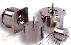
The VM series of Voice Coil Motors are designed as actuator components with incorporated
shafts and sliding bearing as standard to ensure accurate guidance of the coil assembly within the magnetassembly; position senors are
not included. In the most applications the coil is the moving part. Optionally the Voice Coil Actuators can be shipped without shaft and bearing and also completey customised versions in other
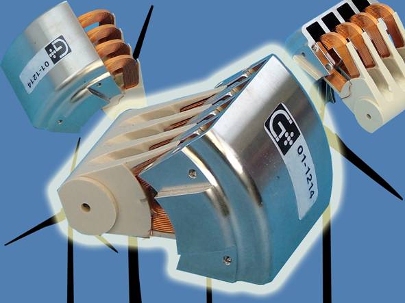
sizes and even formfactors are available (e.g. like short stroke U-shape ironless motors or rotary versions).
The most important characteristics of Voice Coil Actuators are:
- proportional position control: variable position 1 to 100mm / up to 45°
- high speed: vibration or marking
- high efficiency: battery powered systems, back-up systems, temperature sensitive media
- controllability: linear or rotary movement with low noise or low shock at mechanical endstop
- low hysteresis: control systems with high repeatability


| Model | Force cont. / peak |
Stroke overall / linear |
Cont. power |
Weight overall / coil |
Dimensions d x h |
Data sheet |
Drawing 3D |
N |
mm |
W |
g |
mm |
.pdf |
igs |
|
| VM1614 | 0.8 / 2 |
5 / 4 |
5 |
15 / 3 |
16 x 14 |
||
| VM2436 | 2.7 / 7.5 |
20 / ? |
12.5 |
95 / 9 |
24 x 36 |
||
| VM2618 | 3.6 / 10 |
8 / 4 |
10 |
60 / 6 |
26 x 18 |
||
| VM2836* | 3.6 / 10 |
8 / 4 |
10 |
60 / 6 |
28 x 36 |
||
| VM3322 | 5.0 / 14 |
6 / 4 |
8 |
140 / 9 |
33 x 22 |
||
| VM3334* | 5.0 / 14 |
6 / 4 |
8 |
140 / 9 |
33 x 34 |
||
| VM3850RB | 7.5 / 24 |
8 / 4 |
7.4 |
225 / 17 |
38 x 51 |
||
| VM4032 | 010 / 27 |
12 / 9 |
12 |
230 / 25 |
40 x 31 |
||
| VM4040* | 010 / 27 |
12 / 9 |
12 |
230 / 25 |
40 x 40 |
||
| VM4632 | 12.5 / 35 |
10 / 5 |
18 |
360 / 22 |
46 x 46 x 32 |
||
| VM5042 | 21 / 55 |
8 / 7 |
24 |
480 / 35 |
50 x 42 |
||
| VM5050* | 21 / 55 |
8 / 7 |
24 |
480 / 35 |
50 x 50 |
||
| VM6340 | 33 / 100 |
8 / ? |
24 |
750 / 40 |
63.1 x 38 |
||
| VM6548 | 24 / 78 |
20 / 13 |
28 |
950 / 90 |
65 x 48 |
||
| VM8054 | 45 /140 |
32 / 15 |
50 |
1,700 / 150 |
80 x 54 |
||
| VM8080* | 45 /140 |
32 / 15 |
50 |
1,700 / 150 |
80 x 80 |
||
| VM102P2 | 200 / 700 |
12 / 10 |
105 |
4,200 / 325 |
102 x 80 |
||
| VM108-2P30** | 230 / 700 |
40 / 30 |
108 |
8,000 / 750 |
108 x 125 |
* Versions with flex-circuit connection (cover and and non moving wires or connector as user interface)
** force / stroke characteristic can be adjusted by differen coil geometry (higher force / shorter stroke)
![]() Characteristics & selection guide of Voice Coil Motors / Voice Coil Actuators Voice Coil Motors Selection
Characteristics & selection guide of Voice Coil Motors / Voice Coil Actuators Voice Coil Motors Selection
![]() Introduction to Voice Coil Motors / Voice Coil Actuators Voice Coil Motors Parameters
Introduction to Voice Coil Motors / Voice Coil Actuators Voice Coil Motors Parameters
![]() Voice Coil Motors / Voice Coil Actuators Catalogue Voice Coil Motors Catalogue
Voice Coil Motors / Voice Coil Actuators Catalogue Voice Coil Motors Catalogue
Voice Coil Motors / Voice Coil Actuators Coil Calculator (.xls) Coil Calculator for Voice Coil Motors
Electrically voice coil motors are single phase motors and can be operated like conventional DC-motors. As other motors also Voice Coil Motors develop voltage while moving (Back-EMF), which is proportional to the relativ velocity of the coil in
the magnet assembly, so that at constant load and energisation a stationary speed would be achvied, if the stroke would be long enough
(like in a DC brushed motor). Because the coil resistance changes with temperature constant force output can only be achieved by current
control.
Connection to the moving coil of a Voice Coil Motor must be implemented with care to ensure reliable operation.
Flexible cable with many fine strands and Silicone Rubber insulation can provide reliable termination. Care should be taken that the leads
are mechanically secured to the moving assembly preferably at some distance from the soldered joints (solder fuses the strands together, and
leads to large stresses being applied to the termination pins, or to fatigue adjacent to the fuesed portion of the wire). The leads should be
carefully routed to minimise stress. A more consistent means of termination is to use a flexible circuit. This is offered as standard in the
VM5050 and the VM2836 devices.
We are happy to work toghether with you on custom solutions!

